|
Candle Flame, by Alex Alvarez
To generate a realistic
candle flame, the first thing to do, of course, is to light a candle
and stare at it. What should become evident are some of the
behavioral and visual elements which define its appearance. In terms
of Maya lingo, a flame looks more like a transparent, incandescent
surface than a nebulous object made out of thousands of particles.
Flames have feathered yet hard edges, a very smoothly gradated
interior, varying transparency and fluid behavior more akin to
liquid or fabric than gas.
Based on these
observations, a technique which will work well for single flames
viewed from close proximity is softbody geometry. This technique
will involve two phases: rigging how the flame behaves and how it
renders. Again, our focus is not on how to create fire, as one would
see in a fireplace/campfire/fireball. Those effects would lend
themselves more to particles than geometry based on Maya's engine.
Ideally we would like to combine both techniques, to create
iso-surfaces from particle masses, a technique which may become
viable via Fluid Dynamics in Maya 4.5. Studios such as PDI have
written propreitary software for this, used for the Dragon's
fireballs in the film 'Shrek', but we'll have to wait.
This tutorial will make
several assumptions about your knowledge of the software as I am
going to try to keep this as short as possible. We will be
addressing modeling, softbodies, goals, springs, fields, lights,
hypershade, render utilities, the connection editor and shader
glow.
1) model a flame using
any technique you choose. The main thing is to be aware of the UV
coordinate space of the flame, and if it is a poly surface, layout
the UVs cleanly so that color ramps can be smoothly applied across
the surface. For my example I created a NURBS curve and revolved it.
Since we will be turning it into a softbody, make sure there are
enough vertices to be able to get smooth dynamic
deformations.
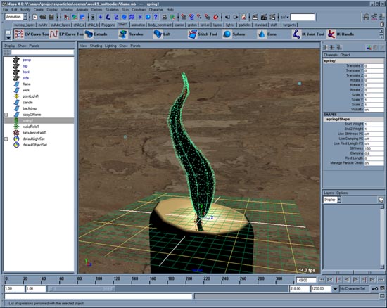
2) turn the flame into
a softbody and design its behavior. Select the flame, open the
'Create SoftBody' dialog window and choose the following options:
Duplicate Make Copy Soft, Hide Original, Make non-soft a goal, and
set the Weight value to '1'. At this point the softbody particles
will not move at all, unless the goal moves, because their goalPP
values are at 1 and the goalWeight value is at 1
3) Use the Component
Editor to set goalPP values so that the particles which surround the
wick of the candle have a high goalPP, such as .8, but the rest of
the particles should have a very low goalPP, such as .2
4) Add a turbulence
field to the particles with a low frequency and animated phase. At
this point the flame will have a 'tear' between the rows of
particles where the goalPP changes from .8 to .2
5) Add 'springs' to the
softbody to give the flame a fluid, clothlike behavior. In the
creation dialog choose 'wireframe' with a value of 2. You will now
begin experimenting with the turbulence field's magnitude,
frequency, phase as well as the spring's stiffness and damping. As
with any use of springs, if your springs 'explode' due to high
attribute values, remember to increase the scene's
'oversampling'.
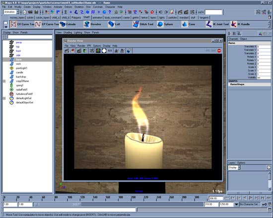
Once finished with the
flame's dynamic animation, it is now time to focus on how it
renders. This will require us to pay special attention to the
brightness, coloring, transparency and edge quality of a flame. A
flame's color tends to be bluish at the base but orangish towards
the tip... sometimes reddish. This can be easily achieved by mapping
the surfaces color with a ramp. A flame also tends to be brighest in
the center. This can be mimicked by turning on Translucency for the
material. It is the transparency which will be a bit more involved. A candle flame is
more transparent in the center than the edges, and more-so at the
base.
First apply the color
ramp to the material color, raise the translucency value, and place
a point light with appropriate color, intensity and decay in the
center of the softbody. You will want the point light to move around
with the flame, so connect the WorldCentroid attribute of the
particleShape node to the Translate vector of the Point light. If
your point light needs to cast shadows, remember to turn off 'casts
shadows' on your flame geometry.
Now on to
transparency.
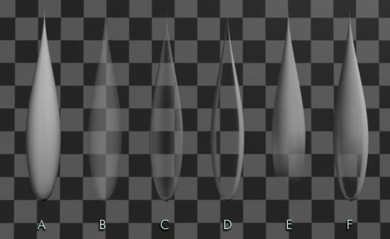
Above we are looking at
six flame surfaces each with a different shader which is controlling
the transparency in a different way. Each shader is Lambert with a
white surface color. Refraction is off.
A) no
transparency
B) Transparency set to 50% gray. This is how Maya
calculates transparency by default. As the transparency approaches
white, the surface fades evenly.
C) Transparency directly
controlled by the Facing Ratio of a Sampler Info Utility
D)
Transparency controlled by a Set Driven Key relationship where the
Facing Ratio of a Sampler Info Utility is the driver.
E)
Transparency directly controlled by a ramp.
F) Transparency
controlled by a multiplication of a ramp by the Set Driven Key
curves generated by a relationship where the Facing Ratio of a
Sampler Info Utility is the driver. Could also be achieved by
connecting the Facing Ratio curves to the Color Gain of a ramp which
is directly connected to the transparency.
While Render Utilities
can seem mysterious due to their lack of documentation, they can
serve a wide range of purposes. In this case we are relying
primarily on the 'Sampler Info Utility'... not to be confused with
the similarly named but completely different 'Particle Sampler
Utility'.
The Sampler Info
Utility (SIU) has several attributes, but one of its 'float'
attributes is called 'Facing Ratio'. This attribute has a value
between 0 and 1 which is determined by the ratio of normals on a
surface to the position of the camera. When the normals are pointing
to the camera, a value of 1 is returned. When the normals are
perpendicular to the line of sight of the camera, the value is 0. By
using the Connection Editor to connect the 'float' Facing Ratio
Output of the SIU to the 'vector' transparency of a material, we
will get a linear relationship between transparency and the facing
ratio.
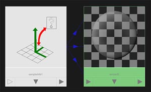
Above we see the
results in Hypershade of making that connection. While the results
are clear on Surface C, the drawback is the lack of flexibilty. What
if you want the opposite effect, where the edges become more
transparent, or what if you want a more dramatic falloff like
Surface D.
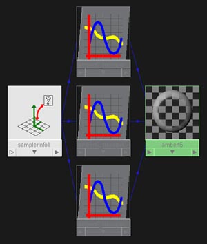
Above we have created a
Set Driven Key relationship where the Facing Ratio is the driver and
the transparency R,G & B are the driven. This way, we can use
curves in the graph editor to control how the falloff is achieved.
The trick to getting this to work is that once you have loaded the
driver and the driven into the Set Driven Key (SDK) window, and have
keyed them to create the relationship curves, you will not be able
to set a second key. This is because you can not manually modify the
driver (facing ratio). Therefore, you end up with 3 curves in the
graph editor when you select the material node, but each curve
(R,G,B) will only have one keyframe at 0,0. At this point you will
need to manually add keys to each curve so that each curve has at
least two keyframes... one at 0,0 and one at 1,1. Once you have this
figured out, you will want to turn on weighted tangents, unlock the
tangent weights of the keyframes, and modify the tangents to control
your transparency falloff based on the facing ratio driver. This
will allow you to achieve results such as surface 'D'
above.
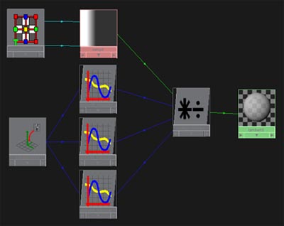
The last step is to
address the fact that not only are a flame's edges more opaque than
the center, but the base of a flame is more transparent than the
top. To achieve this, once the Set Driven Key/SIU relationship has
been made, disconnect the outputs of the SDK curves from the
material. Then create a ramp and a Multiply/Divide Utility. Connect
the ramp's 'color output' to the Multiply node's 'input one', and
connect the SDK curves to 'input two'. Then connect the output of
the Multiply node to the materials transparency. If you wish, you
can avoid using the Multiply node if you connect the SDK curves to
the 'color gain' of the ramp node.

The final step in this
process will be to apply Shader Glow. Above we see the progressive
results of adding glow. The left-most image is without glow, but our
SIU based transparency is evident. Once glow is enabled, our
geometry remains, but this is optional. By turning on 'Hide Source',
the actual geometry will not render; just the glow. This is a great
technique which works well for the candle flame, but is not limited
to it, of course. Even ghosts can be successfully achieved using a
similar workflow to what we have been doing.
When glow is enabled,
there are some important things to know about the Shader Glow node.
In the multilister/hypershader is a Shader called Shader Glow which
controls the look of -all- materials which have glow enabled. If you
need different glow looks for different objects in your scene, you
will need to render in passes. Furthermore, there are many
attributes which can be tweaked to design the look of the glow, one
of which is called Threshold. In the above image, the 3 right images
have Threhold values of 0, .08, and .04. Threshold clips the
luminance values which get glow applied and is clearly a very useful
attribute to help design the desired look. Another important
attribute to change is Auto Exposure which is on by default. This
can cause glow to flicker in an animation, so it is best turned off.
Doing this may cause your glow to get blown out, at which point you
simply need to lower the glow & halo intensities on the Shader
Glow node.
Another issue to raise
is that we have chosen to create the candle by mapping the flame
surface's color, not its incandecance. The is because we are relying
on translucency to brighten the flame. If you need to use
incandecance, remember that areas which are transparent will render
brightly if that region has a high incandecance value. Therefore you
would also want to use the SIU to map the incandecence, but with the
reverse values.
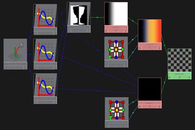
Above we have the graph
of a shader which is using incandecence to determine the brightness
of the flame. The same SIU SDK curves are being used for both
transparency and incandecence. But for the incandecence, the SDK
curves are first going through a Reverse utility.
So that about wraps it
up... If you are unfamiliar with any of the tools used, it is a good
idea to get comfortable with them individually, before trying to
recreate my results immediately. The more unknown things you throw
together, the harder it will be to problem solve.
|